

How can we help you?

How can we help you?
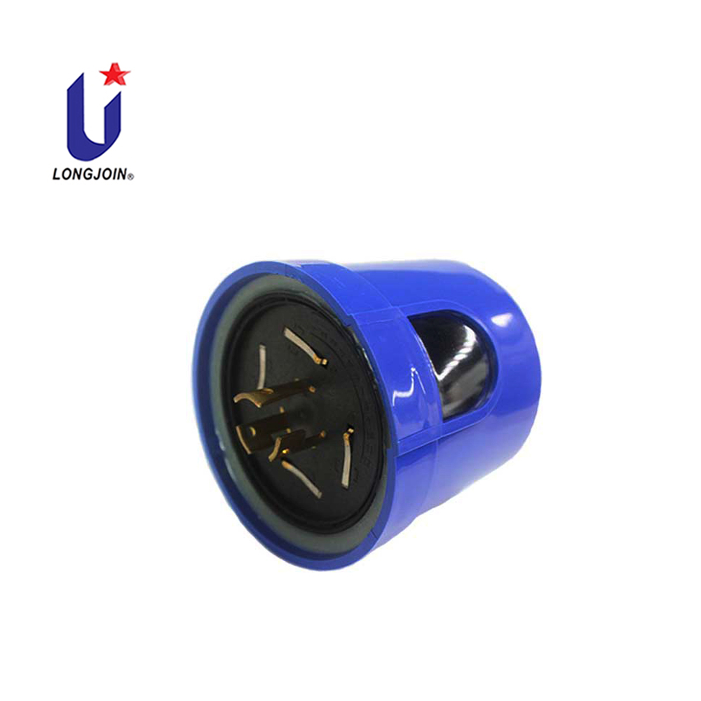
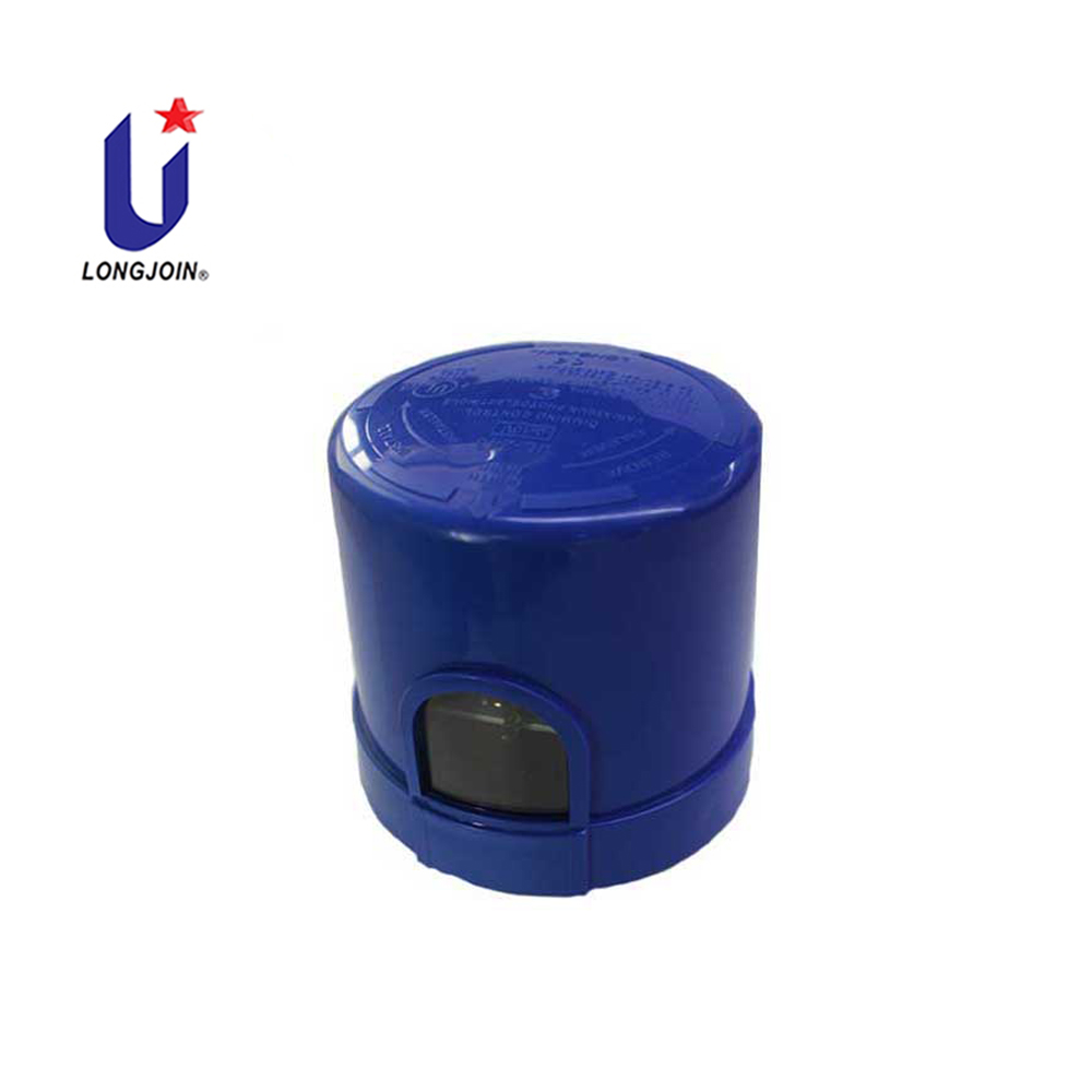

The outdoor light dusk to dawn sensor JL-244 series is applicable to control any independent LED home/street lighting with 0-10V automatically in accordance with the ambient natural lighting level, as well as remote control by using a gateway box (JL-244P or JL-244V) connected to a smart phone either iOS and Andriod OS with Bluetooth communication, while connected to the smart control (JL-244C) with Zigbee communication.
This smart control JL-244C is designed with microprocessor circuits with IR-filtered silicone sensor, a heavy duty surge arrester (MOV) 40kA is provided to protect the lamp from inrush current as well as impulse by lightening.
Further, a preset 3-5 seconds time-delay prevents excessive operation due to spotlight or lightning during the night time. A heavy duty relay supports the work life of over 15,000 cycles,.
This smart control JL-244C provides twist lock terminals and signal contacts, in 7P, meeting the requirements of ANSI C136.41-2013, as well as being listed by UL under the Standard for Plug-In, Locking Type Photo control for Use with Area Lighting ANSI/UL773.
JL-244 Nema 7 Pin 0-10V Dimming Photocell Addvantages:
ANSI C136.41-2013 Twist Lock
0-10V Dimming
Multi-Volts Application
IP65 Ready / IP67 Optional
40kA Surge Arrester Built-in
IR filtered Photodiode Sensor
Midnight Dimming*
LED Decay Compensation Featured**
Fail-On Mode
Metal Armor for Long Life
Product 0-10V Dimming Features:
-Constant On/Off Dimming
Standard program for LED output keeping the field lit with
constant lighting level, in accordance with the natural sunlight
level detected. When the natural lighting is higher than 110% of
the rated level, hot line will be disconnected to keep LED fixture
as zero consumption
Available with JL-241C, JL-242C and JL-243C.

-Midnight Dimming
Standard program for LED output lowered to a customized percentage
to save power after midnight until about 1 hour before dawn time,
as well as reduce light pollution to environment.
Available with JL-242C and JL-243C.

-LED Decay Compensation
Standard program for LED output partially reserved and to be used
for compensating decay over a work time up to 13 years. It will
extend the work life of a LED fixture significantly.
Available JL-243C only
| Model | JL-241 | JL-242 | JL-243 |
| Constant On/Off Dimming | ● | ● | ● |
| Midnight Dimming | × | ● | ● |
| LED Decay Compensation | × | × | ● |
| Rated Voltage | 110-277VAC, 50/60Hz | ||
Applicable Voltage Range | 90-305VAC, 50/60Hz | ||
| Rated Loading | 1000W Tungsten, 1800VA Ballast, 5A e-Ballast | ||
| Power Consumption | 1.2W Average | ||
| Typical On/Off Level | 50 Lux | ||
| Typical Surge Protection | 640 Joule / 40000 Amp | ||
| Typical Time Delay | 10 Sec | ||
| Typical IP Protection | IP65 | ||
Dielectric Strength | 5000 Vrms | ||
| Ambient Temp. | -40 ~ +70 ℃ | ||
| Related Humidity | 99% | ||
| Overall Size | 84(Dia.) x 86mm | ||
| Weight Approx. | 200 gr | ||
-Note:
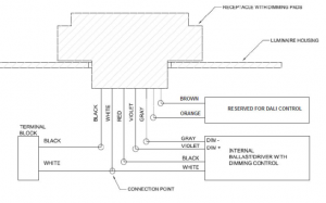
When used with JL-241C/242C/243C, either a 5 pin or
7 pin NEMA receptacle is applicable, with Gray and Violet
leads connected to a 0-10V/1-10V driver while power leads
connected.


Longjoin Photocell have Multi-Certifications:UL/CE/LVD
You can Click to Check the Certifications Page to Confirm:
Disconnect power; wire the color coded receptacle according to the diagram below.
Push the photocontroller on and twist it clockwise to lock it into the receptacle.
Install the photocontroller with the Photocell facing the NORTH direction as indicated on the top of the photocontroller.
Adjust the receptacle position if necessary.
It is normal for the SWITCH to take several minutes to turn off when first installed.
To test “turn on” during daytime, cover its eye with sliding the metal strip mounted.
Do not cover with finger because light traveling through fingers may be great enough to keep the switch open.
Test will take approximately 2 minutes.


Copyright Longjoin Electronics Co., Ltd. Shanghai 2008. All Rights Reserved
沪ICP备2022000883号-1

